Haryana State Board HBSE 10th Class Science Solutions Chapter 12 Electricity Textbook Exercise Questions and Answers.
Haryana Board 10th Class Science Solutions Chapter 12 Electricity
HBSE 10th Class Science Electricity Textbook Questions and Answers
Question 1.
A piece of wire of resistance R is cut into five equal parts. These parts are then connected in parallel. If the equivalent resistance of this combination is R’, then the ratio R / R is ………
(a) 1/25
(b) 1/5
(c) 5
(d) 25
Answer:
(d) Resistance of each part = \(\frac{R}{5}\)
When the five parts are connected in parallel, the equivalent resistance R’ is given by
\(\frac{1}{R^{\prime}}=\frac{5}{R}+\frac{5}{R}+\frac{5}{R}+\frac{5}{R}+\frac{5}{R}=\frac{25}{R}\)
∴ \(\frac{\mathrm{R}}{\mathrm{R}^{\prime}}=25\)
![]()
Question 2.
Which of the following terms does not represent electrical power in a circuit?
(a) I²R
(b) IR²
(c) VI
(d) V²/R
Answer:
(b) IR²
Question 3.
An electric bulb is rated 220 V and 100 W. When it is operated on 110 V, the power consumed will be ………………
(a) 100W
(b) 75W
(c) 50W
(d) 25W
Answer:
Resistance \(R=\frac{V^2}{P}=\frac{(220)^2}{100}=484 \Omega\)
When operated on 110 V, the power consumed will be \(P^{\prime}=\frac{V^{\prime 2}}{R}=\frac{(110)^2}{484}=25 \mathrm{~W}\)
Question 4.
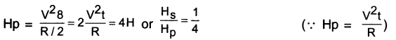
Two conducting wires of the same material and of equal lengths and equal diameters are first connected in series and then parallel in a circuit across the same potential difference. The ratio of heat produced in series and parallel combinations would be …………….
(a) 1:2
(b) 2:1
(c) 1:4
(d) 4:1
OR
Two Identical wires are first connected in series and then In parallel to a source of supply. Find the ratio of the heat produced in two cases.
Answer:
(c) 1:4
Let R be the resistance of each wire. In senes combination, the total resistance will be 2R. Heat produced,

In parallel combination, the total resistance is R/2. Heat produced.
![]()
Question 5.
How is a voltmeter connected in the circuit to measure the potential difference between two points?
Answer:
A voltmeter is always connected in parallel connection with the circuit.
Question 6.
A copper wire has a diameter 0.5 mm and a resistivity of 1.6 x 10⁻⁸ Ωm. What will be the length of this wire to make its resistance 10Ω? How much does the resistance change if the diameter is doubled?
Answer:
Given the diameter of the wire,
d = 0.5mm = 0.5 x 10m=5 x 10m
Resistivity of copper p = 1.6 x 10 Qm
Required resistance R = 10
Length I = ?
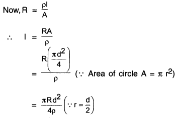
Conclusion: When diameter d is doubled, then resistance R becomes one-fourth of its original value.
![]()
Question 7.
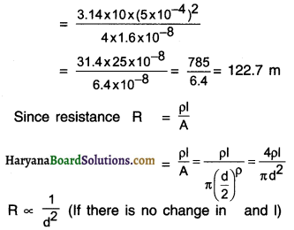
The values of current I flowing in a given resistor for the corresponding values of potential difference V across the resistors are given below.

Plot a graph between V and I and calculate the resistance of that resistor.
Answer:
1. The graph between V and I plotted by using the given data is shown here.
2. Since the graph is a straight line, the slope of the graph will be reciprocal of resistance. \(\left(\text { i.e., } \frac{1}{R}\right)\), because the slope of the graph \(=\frac{\Delta \mathrm{I}}{\Delta \mathrm{V}}=\frac{1}{\mathrm{R}}\)
Question 8.
When a 12 V battery is connected across an unknown resistor, there is a current of 2.5 mA in the circuit. Find the value of the resistance of the resistor.
Answer:
Here,v=12V, l=2.5 mA = 2.5 x 10⁻³A; R=?
The resistance of the resistor R = \(\mathrm{R}=\frac{\mathrm{V}}{\mathrm{l}}=\frac{12}{2.5 \times 10^{-3}} \)
= 4800 Ω = 4.8 kΩ
Question 9.
A battery of 9 V is connected in series with resistors of 0.2 Ω, 0.3 Ω, 0.4 Ω, 0.5 Ω and 12 Ω, respectively. How much current would flow through the 12 Ω resistor?
Answer:
Since all the given resistors are connected in series, their equivalent resistance
Rs = 0.2 + 0.3 + 0.4 + 0.5 + 12 = 13.4Ω
The current through the circuit,
\(\mathrm{I}=\frac{\mathrm{V}}{\mathrm{R}_{\mathrm{S}}}=\frac{9}{13.4}=0.67 \mathrm{~A}\)
In a series combination, the equal amount of current I flows through all the resistors, so the current flowing through 12 Ω resistor = 0.67 A
![]()
Question 10.
How many 176 Ω resistors (In parallel) are required to carry 5 A on a 220 V line?
Answer:
Here, I = 5A; V = 220 V
∴ The total resistance of the given circuit is Rtotal = \(\frac{\mathrm{V}}{\mathrm{l}}=\frac{220}{5}=44 \Omega\)
So, when 44 Ω resistance is connected with 220 v line, 5A current would flow through the given circuit. Now, suppose ‘n’ resistors, each of resistance R, are required to be connected in parallel, so that the total resistance Rtotal becomes 44 Ω.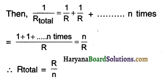
Thus, when we connect 4 resistors each of 176 in parallel, it will give the total resistance of 44. This will allow 5A current to flow when connected to 220 V line.
Question 11.
Show how you would connect three resistors, each of resistance 6Ω, so that the combination has a resistance of
(i) 9Ω, (ii) 4Ω.
Answer:
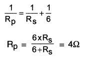
(i) For getting total resistance of 9Ω from three resistors each of 6Ω, we
(a) First connect two 6Ω resistors in parallel.
(b) Then, we connect this parallel combination in series with the third 6Ω resistors as shown in
For resistors connected in parallel,
\(\frac{1}{R_p}=\frac{1}{R_1}+\frac{1}{R_2}=\frac{1}{6}+\frac{1}{6}=\frac{2}{6}=\frac{1}{3}\)
∴ Rp = 3Ω

Now, total resistance HaryanaBoardSolutio
= Resistance in parallel + 6 Ω of resistance connected in series.
= Rp+6Ω
= 3Ω + 6Ω = 9Ω
![]()
(iii) For getting total resistance of 4Ω from three resistors each of 6Ω, we
(a) First connect two 6Ω resistors in series
(b) Then, we connect this senes combination in parallel to the third 6Ω resistor as shown in the diagram.
For resistors connected in series,
For resistors connected in series,
Rs = 6 + 6 = 12 Ω
Now, for total resistance
Question 12.
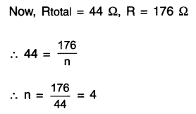
Several electric bulbs designed to be used on a 220 V electric supply line, are rated 10 W. How many lamps can be connected In parallel with each other across the two wires of 220 V line if the maximum allowable current is 5 A?
Answer:
Voltage rating of each bulb = 220 V
Power rating of each bulb = 10 W
∴ The resistance of each bulb
\(R=\frac{V^2}{P}=\frac{220^2}{10}=\frac{220 \times 220}{10}=4840 \Omega\)
Now, V = 220 v and I = 5A
∴ The total resistance of the given circuit is
\(\text { Rtotal }=\frac{V}{l}=\frac{220}{5}=44 \Omega\)
Thus, when 44Ω resistance is connected with 220 V line, 5A current flows through the given circuit.
So, when ‘n’ bulbs each having resistance R, are connected in parallel, their equivalent resistance
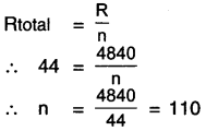
Thus, 110 bulbs each having resistance 4840Ω connected in parallel will give total resistance of 44 Q causing a current of 5 A to flow when we connect them to 220 V line.
Question 13.
A hot plate of an electric oven connected to a 220 V line has two resistance coils A and B, each of 24Ω resistance, which may be used separately, In series, or in parallel. What are the currents In the three cases?
Answer:
Potential difference V = 220 V
Resistance of each coil RA = RB 24 Ω
Case-1: When coil A or B is connected separately, the current through each coil is
\(I=\frac{V}{R_A} \text { or } \frac{V}{R_B}=\frac{220}{24}=9.166 \mathrm{~A}\)
Case-2: When the coils A and B are connected in series, the equivalent resistance of the circuit
RS = RA + RB = 24 + 24 = 48Ω
Now, the current through the series combination
\(\text { Is }=\frac{V}{R_s}=\frac{220}{48}=4.58 A \approx 4.6 \mathrm{~A}\)
![]()
Case-3: When the coils A and B are connected in parallel, the equivalent resistance RP of the circuit is given by
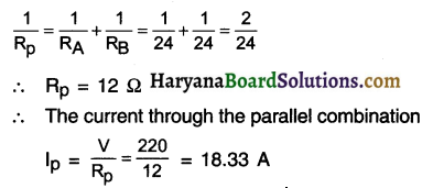
Question 14.
Compare the power used In the 2Ω resistor in each of the following circuits:
(i) a 6 V battery in series with 1Ω and 2Ω resistors, and
(ii) a 4 V battery in parallel wIth 12Ω and 2Ω resistors.
Answer:
(i) 1Ω resistor and 2Ω resistor are connected in series.
∴ The equivalent resistance Rs = 1 + 2 = 3 Ω
Now, the voltage of the battery V = 6V
So, the current flowing through the circuit,
\(I s=\frac{V}{R_s}=\frac{6}{3}=2 A\)
In a series combination equal current 2 A flows through each resistor.
Hence, the current flowing through 2Ω resistor is also 2A.
∴ Power used in 2Ω resistor
P1 =I2sR
= (2)2 x 2 = 8W
(ii) 12Ω resistor and 2Ω resistor are connected in parallel. A 4 V battery is connected in parallel with this parallel combination of resistors. The potential difference across 2Ω resistor will also be 4V.
∴ Power used in 2Ω resistor –
\(P 2=\frac{V^2}{R}=\frac{4^2}{2}=\frac{16}{2}=8 \mathrm{~W}\)
For comparing the power used in 2Ω resistor in two different circuits, we find the ratio of P1 and P2.
∴ \(\frac{P_1}{P_2}=\frac{8}{8}=1\)
∴ P1 = P2
Hence, we conclude that 2Ω resistor uses equal power i.e. 8W in both the circuits.
![]()
Question 15.
Two lamps, one rated 100 W at 220 V, and the other 60 W at 220 V, are connected in parallel to electric mains supply. What current is drawn from the line If the supply voltage is 220 V?
Answer:
Resistance of 100 w lamp,
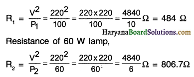
When, these lamps are connected in parallel, their equivalent resistance Rp would be
Question 16.
Which uses more energy, a 250 W TV set in 1 hr, or a 1200 W toaster in 10 minutes?
Answer:
(a) For TV set:
P=250W = 25\(\frac{\mathrm{J}}{\mathrm{s}}\)
Time t = 1h = 3600s
Electric energy (used by TV set)
= P x t
= 250\(\frac{\mathrm{J}}{\mathrm{s}}\) x 3600s
= 900000 = 900kJ
(b) For toaster:
Power P = 1200 W = 1200\(\frac{\mathrm{J}}{\mathrm{s}}\)
Time t = 10 minute = 10 x 60 = 600 s
Electric energy (used by toaster) = P x t
= 1200\(\frac{\mathrm{J}}{\mathrm{s}}\) x 600 s = 720000 720 kJ
Thus, we can say a 250 W TV set in 1 h consumes more electric energy than a 1200W toaster in 10 minute.
Question 17.
An electric heater of resistance 8 Q draws 15 A from the service mains 2 hours. Calculate the rate at which heat is developed In the heater.
Answer:
Here, I = 15A; R = 8Ω; t = 2h
The rate at which heat is developed in the heater means its electric power,
P =I2R=(15)2 x 8 = 225 x 8=1800W=1800\(\frac{\mathrm{J}}{\mathrm{s}}\)
Question 18.
Explain the following.
(a) Why is tungsten used almost exclusively for filament of electric lamps?
(b) Why are the conductors of electric heating devices, such as bread-toasters and electric irons, made of an alloy rather than a pure metal?
(c) Why is the series arrangement not used for domestic circuits?
(d) How does the resistance of a wire vary with its area of cross-section?
(e) Why copper and aluminium wires are most widely employed for electricity transmission?
Answer:
(a) Tungsten metal has a very high melting point of 3380°C and so it does not melt even at very high temperature.
- Tungsten has the ability to retain much of the heat generated. So, when it becomes very hot it emits light without getting melted.
- Tungsten is very flexible and can be easily molded into filament.
- Owing to all these reasons, tungsten is the only metal used in filament of electric lamps.
![]()
(b) Compared to metals, alloys have very high resistance. This helps in better heat generation. Hence,
(c) In a series connection, the voltage gets divided. Due to this, the appliances give less output.
If fault occurs in one appliance or at one part of the circuit, the current stops flowing in the entire circuit and other appliances also stop working.
- All the electrical appliances connected in a series are operated by one single switch. So, we cannot control individual appliance.
- Owing to all these reasons, we cannot use series connection for domestic use.
(d) The resistance R of a wire is inversely proportional to its cross-section area A i.e. R α \(\frac{1}{A}\)
- So, thicker the wire (i.e. larger the cross-section area) lesser the resistance and vice-versa.
(e) Copper and aluminium have low electric resistivity. So, they can conduct electric current without much heat loss.
- Compared to other metals copper and aluminium are cheaper. Moreover, wires can be easily drawn from these metals.
HBSE 10th Class Science Electricity InText Activity Questions and Answers
Textbook Page no – 200
Question 1.
What does an electric circuit mean?
Answer:
A continuous and closed path along which electric current flows is called an electric circuit.
Question 2.
Define the unit of current.
Answer:
Electric current:
1. The rate of flow of electric charge is known as electric current. In other words, the net quantity of electric charge that flows through any cross-section of a conductor is known as the electric current.
2. Thus, electric current \(=\frac{\text { Quantity of electric charge }}{\text { Time }}\)
3. Thus, if Q is the amount of electric charge passing through any cross-section of a conductor in time t then, electric current (I) =\(\frac{Q}{t}\)
4. If a quantity of one Coulomb (1Q) electric charge passes through the conductor in 1 second, then we can say that an electric current of one ampere (1 A) is flowing through the conductor.
5. SI unit of electric current is Coulomb/second (C/s).
6. Electric current is also measured in Ampere (A), after the French scientist Andre-Marie Ampere.
7. Milliampere (mA) and microampere (μA) are smaller units to measure electric current.
8. 1 mA = 10-3 A and 1 μA = 10-6A.
9. An instrument called Ammeter ¡s used to measure the electric current.
![]()
Question 3.
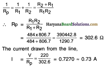
Calculate the number of electrons constituting one coulomb of charge.
Answer:
Charge on 1 electron = 1.6 x 10⁻¹⁹C
Also, total charge Q = 1C
But, Q = ne
∴ Number of electrons
Thus, 625 x 1018 electrons will constitute 1 coulomb of charge.
Textbook Page no – 202
Question 1.
Name a device that helps to maintain a potential difference across a conductor.
Answer:
An electric cell or battery is a device that helps to maintain potential difference across a conductor.
Question 2.
What is meant by saying that the potential difference between two points is 1 V?
Answer:
If the work done to bring 1 coulomb electric charge from one point to another is 1 joule, then the potential difference between these two points is called 1 volt.
Thus, 1 volt = \(\frac{1 \text { joule }}{1 \text { Coulomb }}\)
Question 3.
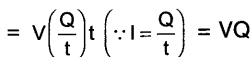
How much energy is given to each coulomb of charge passing through a 6 V battery?
Answer:
Each coulomb means every 1 coulomb i.e.
Q = 1 coulomb
Potential difference V = 6 volt
Energy = work done i.e. W =?
Work done W = V.Q.
= 6 V.1C
= 6J
Thus, 6 J energy is given to each coulomb of charge passing through a 6v battery.
Textbook Page no – 209
Question 1.
On what factors does the resistance of a conductor depend?
Answer:
The resistance of a conductor depends
- on its length,
- on its area of cross-section,
- its temperature and
- on the nature of its material
Question 2.
Will current flow more easily through a thick wire or a thin wire of the same material, when connected to the same source? Why?
Answer:
The current will flow more easily through a thick wire as compared to a thin wire.
Reason:
- Resistance \(\mathrm{R} \propto \frac{1}{\text { Cross – section A }}\) This means larger the value of A, lesser will be the value of resistance R.
- Thick wire will have more cross-section area compared to the thin-wire and so its resistance will be lower.
Question 3.
Let the resistance of an electrical component remain constant while the potential difference across the two ends of the component decreases to half of its former value. What change will occur in the current through it?
Answer:
According to Ohm’s law, I = \(\frac{\mathrm{V}}{\mathrm{R}}\). It is given that R = constant. ∴ I α V
Since I is directly proportional to potential difference V, if the value of V is halved, the value of current I will also become half.
![]()
Question 4.
Why are coils of electric toasters and electric irons made of an alloy rather than a pure metal?
Answer:
The coils of electrical heating devices such as toaster and electric iron are made of alloys such as nichrome and not of pure metals due to following reasons:
(i) Alloys have higher resistivity as compared to pure metals. This helps in easily controlling the heat
to be produced.
(ii) Alloys do not oxidize i.e. they burn readily at high temperature.
(iii) Alloys have high melting point compared to several metals.
Question 5.
Use the data of Table 12.2 to answer the following.
(a) Which among iron and mercury is a better conductor?
(b) Which material is the best conductor?
Answer:
(a) The electrical resistivity of iron is 10.0 x 10⁻⁸ Ω m whereas that of mercury is 94 x 10-8 Ωm.
Lesser the resistivity, more will be the conduction of electricity. Hence, iron (Fe) is a better conductor than mercury (Hg).
(b) In the entire table, silver has the lowest electrical resistivity of just 1.60 x 10⁻⁸ Ωm. Hence, silver metal is the best conductor of electricity.
Textbook Page no – 213.
Question 1.
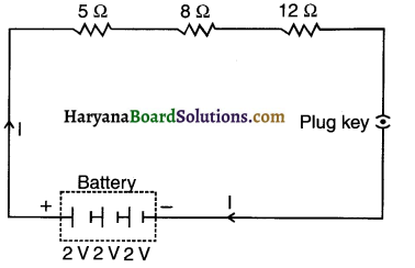
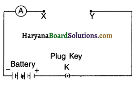
Draw a schematic diagram of a circuit consisting of a battery of three cells of 2 V each, a 5Ω resistor, an 8Ω resistor, and a 12Ω resistor, and a plug key, all connected in series.
Answer:
The required circuit diagram is as shown in the adjoining figure.
Question 2.
Redraw the circuit of Question 1, putting in an ammeter to measure the current through the resistors and a voltmeter to measure the potential difference across the 12Ω resistor. What would be the readings in the ammeter and the voltmeter?
Answer:
The required circuit diagram is as shown here:
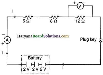
Total voltage i.e. Potential difference V = 3 x 2 = 6V
Total resistance, Rs = 5 + 8 + 12 = 25Ω
Reading of ammeter, I =\(\frac{6}{25}\)= 0.24 A.
Reading of voltmeter,
V = l x R = 0.24 x 12 = 2.88V.
![]()
Textbook Page no – 216.
Question 1.
Judge the equivalent resistance when the following are connected in parallel –
(a) 1Ω and 106Ω,
(b) 1Ω and 103 Ω,and 106 Ω.
Answer:
(a) In both cases equivalent resistance will be less than 1Ω but approximately 1Ω.
Reason:
- As per the characteristic of parallel connection, when resistors are connected in parallel, the equivalent resistance is less than the least resistance.
- Here, in case (a) as well as (b), the lowest resistance value is of 1Ω. So, naturally, the value of equivalent resistance can be judged as lesser than 1Ω.
Question 2.
An electric lamp of 100Ω, a toaster of resistance 50Ω, and a water filter of resistance 500Ω are connected In parallel to a 220 V source. What is the resistance of an electric iron connected to the same source that takes as much current as all three appliances, and what is the current through it?
Answer:
Resistance of electric lamp, R1 = 100Ω
Resistance of toaster, R2 = 50Ω
Resistance of water filler, R3 = 500Ω
Equivalent resistance Rp of the three appliances connected in parallel is given by
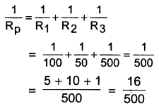
\(=\frac{500}{16}=\frac{125}{4}\)
= 31.25Ω
Resistance of electric iron = Equivalent resistance of the three appliances connected in parallel
= 31.25Ω
Applied voltage, V = 220 V
Current, \(\mathrm{I}=\frac{\mathrm{V}}{\mathrm{R}}=\frac{220 \mathrm{~V}}{31.25 \Omega}=7.04 \mathrm{~A}\)
Question 3.
What are the advantages of connecting electrical devices in parallel with the battery instead of connecting them in series?
Answer:
| Series Connection | Parallel Connection |
| 1. When two or more resistors are connected end to end consecutively, such a connection is called a series connection. | When two or more resistances are connected between the same two points, they are said to be connected in parallel (because they become parallel to each other). |
| 2. In series connection, the resistors are connected across two points say A and B of the circuit in such a way that equal amount of current flows through each resistor and the current flows in only one path. | In parallel connection, the resistors are connected across two points say A and B of the circuit in such a way that equal amount of voltage drops across two ends of each resistor and the current flows in more than one path. |
| 3. The magnitude of equivalent resistance R is always larger than the largest resistance of the circuit. | In parallel connection, voltage drop (V) across two ends of each resistor remains same but the current (I) that flows in the circuit gets divided into three parts at point A. |
| 4. Here, equivalent resistance R = R1+R2+R3 | Here, equivalent resistance =\(\frac{1}{R}=\frac{1}{R_1}+\frac{1}{R_2}+\frac{1}{R_3}\) |
| 5. The magnitude of equivalent resistance R is always larger than the largest resistance of the circuit. | The magnitude of equivalent resistance I is always smaller than the smallest resistance. |
![]()
Question 4.
How can three resistors of resistances 2Ω, 3Ω, and 6Ω be connected to give a total resistance of (a) 4Ω (b)1Ω?
Answer:
(a) First connect resistors of 3Ω and 6Ω in parallel connection.
Then connect 2Ω resistor in series connection with the above-mentioned two resistors.
The connection is shown in the diagram below:
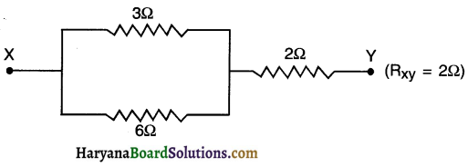
Resistance in parallel connection, Rp
\(=\frac{1}{R_1}+\frac{1}{R_2}=\frac{R_1 R_2}{R_1+R_2}=\frac{3 \times 6}{3+6}=2\)
Resistance between parallel connection Rp and third resistor R3 will be
Rs= Rp+R3 = 2 + 2 = 4Ω
Thus, RXY gives us a total resistance of 4Ω using resistors of 2Ω 3Ω and 6Ω.
(b) On connecting all the three resistors, the diagram we get is as follows:
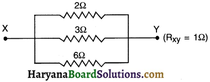
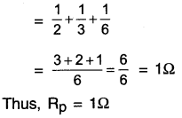
Total resistance in this parallel connection \(\frac{1}{R_p}=\frac{1}{R_1}+\frac{1}{R_2}+\frac{1}{R_3}\)
Question 5.
What is (a) the highest, (b) the lowest total resistance that can be secured by combinations of four coils of resistance 4Ω, 2Ω, 8Ω, 12Ω, 24Ω?
Answer:
(a) The highest resistance can be obtained by connecting all the four coils in series. In this case,
Rs =R1+R2+R3+R4 = 4 + 8 + 12 + 24 = 48
Thus, the highest resistance which can be secured is 48Ω.
(b) The lowest resistance can be secured by connecting all the four coils in parallel. In this case,

Thus, the lowest resistance which can be secured is 22.
Textbook Page no – 218.
Question 1.
Why does the cord of an electric heater not glow while the heating element does?
Answer:
1. The heating element of the electric heater is made up of an alloy such as nichrome. It has high resistance. So, it becomes red hot on heating and starts glowing,
2. The cord is made of pure metal like copper which has very low resistance. So when electricity is passed through it, it does not become red hot and so it does not glow.
Question 2.
Compute the heat generated while transferring 96000 coulombs of charge in one hour through a potential difference of 50V.
Answer:
Here, charge, Q = 96000 C,
Time t =1 h=60 x 60 = 3600s.
Potential difference V = 50 V
Now, Heat generated H = Vlt
= 50 x 96000 = 4800000 J = 4.8 X 10⁶ J
Or
=4.8 x 103 x 103J=4.8 x 10³ kJ = 4800 kJ
Question 3.
An electric iron of resistance 20Ω takes a current of 5 A. Calculate the heat developed in 30 s.
Answer:
Here, current I = 5A
Resistance R = 20 , time t = 30 s
Now,
Heat produced H = I2Rt
= (5)2 x 20 x 30 = 25 x 20 x 30
=15000J = 15kJ
Textbook Page no – 220.
Question 1.
What determines the rate at which energy is delivered by a current?
Answer:
The electric current remains the same. So, it is the type of resistance placed in the circuit that determines the rate at which energy is delivered by the current.
![]()
Question 2.
An electric motor takes 5 A from a 220 V line. Determine the power of the motor and the energy consumed in 2 h.
Answer:
Here, I = 5A,V = 220 V
T= 2h = (2 x 60 x 60) s= 7200 s
Power P = VI = 220 x 5 = 1100W = 1100J/s
Now,
Energy consumed W = Pt = 1100 J/s x 7200 s
= 7920000 J = 7.92 x 10⁶ j
Activities
Activity 1.
Discuss the factors on which strength of electric current in a given conductor depends.
OR
How can you say that the current flowing in a circuit is strong or weak? Discuss.
Answer:
Ohm s law says, current (I) = \((\mathrm{I})=\frac{\mathrm{V} \text { (Potential difference) }}{\mathrm{R} \text { (Resistance) }}\)
From this relation we draw two conclusions. They are –
(i) I α V (It R = constant) (ii) I \(\frac{1}{R}\)(if V = constant)
From 1st:
- Since, current (I) is directly proportional to potential difference V, it value of V is doubled, the current (I) flowing through it will also get doubled.
- It V is halved, the current will also get halved.
From 2nd:
- Current (I) is inversely proportional to resistance (R). So, if the value of resistance is doubled, the current (I) flowing will get halved.
- If resistance is halved, the current (I) will get doubled.
Conclusion:
1. The strength of electric current in a given conductor depends on –
(i) Potential difference (V) across the ends of the conductor (ii) Resistance (R) of the conductor
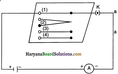
Activity 2.
Aim: To show that the strength of an electric current in a circuit depends on the resistance used in the circuit.
Answer:
1. Take a nichrome wire, a torch bulb, a 10 W bulb and an ammeter (0 – 5A range), a plug key and some connecting wires.
2. Set up the circuit by connecting four dry cells of 1.5 V each in series with the ammeter leaving a gap
XV in the circuit, as shown in Fig.
3. Complete the circuit by connecting the nichrome wire in the gap XV. Plug the key. Note down the ammeter reading. Take out the key from the plug. [Note: Always take out the key from the plug after measuring the current through the circuit.
4. Replace the nichrome wire with the torch bulb in the circuit and find the current through It by measuring the reading of the ammeter.
5. Now repeat the above step with the lo W bulb in the gap XY.
6. Are the ammeter readings different for different components connected in the gap XV? What do the above observations indicate?
7. You may repeat this activity by keeping any material component in the gap. Observe the ammeter readings in each case. Analyze the observations.
Observation:
- Yes, the ammeter readings are different for different components (Nichrome wire, a torch bulb and a low bulb) when connected in the gap XY.
- This happened because certain components offer an easy path for the flow of electric current while the others resist the flow. This means that the current through an electric component depends on its resistance.
Activity 3.
Procedure: To study the factors on which resistance of conducting wire depends.
Procedure:
Complete an electric circuit consisting of a cell, an ammeter, a nichrome wire of length I [say, marked (1)] and a plug key, as shown in figure.
1. Now, plug the key. Note the current in the ammeter.
2. Replace the nichrome wire by another nichrome wire of same thickness but twice the length, that is 21 [marked (2) in the Fig.
3. Note the ammeter reading.
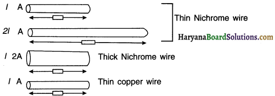
4. Now replace the wire by a thicker nichron wire, of the same length I [marked (3)]. A thicker wire has larger cross-sectional area. Again note down the current through the circuit.
5. Instead of taking a nichrome wire, connect copper wire (marked (4) in Figure] in the circuit.
6. Let the wire be of the same length and same area of cross-section as that of the first nichrome wire [marked (1)1. Note the value of the current.
![]()
7. Notice the difference in the current in all cases.
8. Does the current depend on the length of the conductor?
9. Does the current depend on the area of cross section of the wire used?
Observation and Conclusion:
From the above activity, we can note the following observations:
- When the length of the wire is doubled, the ammeter reading decreases to one-half of its initial value.
- When we use a thicker wire of the same material and of the same length, the current in the circuit increases.
- When we use copper wire of similar dimensions in place of nichrome wire, the current is the circuit increases.
Thus we conclude that the resistance of a conductor depends
- on its length,
- on its area of cross-section and
- on the nature of its material.
Activity 4.
Aim: To study the series combination of resistors.
1. Join three resistors of different values in series. Connect them with a battery, an ammeter and a plug key, as shown in figure. You may use the resistors of values like 1Ω, 2Ω, 3Ω etc., and a battery of 6 V for performing this activity.
2. Plug the key. Note the ammeter reading.
3. Change the position of the ammeter to anywhere in between the resistors. Note the ammeter reading each time.
4. Do you find any change in the value of current through the ammeter?
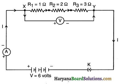
Observation and conclusion:
- The ammeter reading is nearly lA. This value remains same irrespective of the position of the ammeter.
This means the current passing through each and every part of circuit is same. - We conclude that in a series connection the current flowing is same throughout the circuit and through each resistor.
Activity 5.
Aim: To show that in a series combination of resistors, the total potential difference across the combination divides itself across the individual resistors.
Answer:
1. In Activity 124, insert a voltmeter across the ends X and Y of the series combination of three resistors, as shown in Fig. 12.16 of text-book.
2. Plug the key in the circuit and note the voltmeter reading. It gives the potential difference across the series combination of resistors. Let it be V. Now measure the potential difference across the two terminals of the battery. Compare the two values.
3. Take out the plug key and disconnect the voltmeter. Now insert the voltmeter across the ends X and P of the first resistor, as shown in Fig. 12.16 of text-book.
4. Plug the key and measure the potential difference across the first resistor. Let it be V1.
5. Similarly, measure the potential difference across the other two resistors, separately. Let these values be V2 and V3, respectively.
6. Deduce a relationship between V, V1, V2 and V3
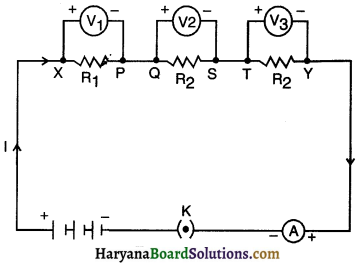
Observation and Conclusion:
1. The potential difference across the series combination is equal to the potential difference across the two terminals of the battery.
2. Potential difference across the first resistor R1 is found out to be V1.
3. Similarly, potential difference across resistors R2: and R3 separately are found out to be V2 and V3 respectively. Moreover, V = V1 + V2 + V3.
4. In a series combination of different resistors, the potential difference across different resistors is different,
i.e. If R1 ≠ R2 ≠ R3, V1 ≠ V2 ≠ V3.
5. The total potential difference across the combination Is equal to the sum of potential difference across each of the resistors, i.e., total potential difference across the combination divides itself across the individual resistors,
i.e. V is equal to V1 + V2 + V3.
Activity 6.
Aim: To study the parallel combination of resistors.
Procedure:
1. Make a parallel combination, XV, of three re&stors having resistances R1, R2, and R3, respectively. Connect it with a battery, a plug key and an ammeter, as shown in Fig. 12.10. Also connect a voltmeter in parallel with the combination of resistors.
2. Plug the key and note the ammeter reading. Let the current be I. Also, take the voltmeter reading. It gives the potential difference V, across the combination. The potential difference across each resistor is also V. This can be checked by connecting the voltmeter across each individual resistor (see Fig. 12.11).
3. Take out the plug from the key. Remove the ammeter and voltmeter from the circuit. Insert the ammeter in series with the resistor R1, as shown in Fig. 12.11. Note the ammeter reading, l.
4. Similarly, measure the currents through R2 and R3. Let these be I2 and I3, respectively. What is the relationship between
I, I1 , I2 , and I3
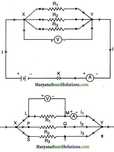
Observation and conclusion:
1. Ammeter showed the reading I when connected. The voltmeter showed reading V when connected.
2. Potential difference across each resistor is same (i.e. V), as across the combination of resistors, i.e., V1 = V2 = V3 = V.
3. Ammeter showed reading li, when connected with the resistor R1.
4. Similarly ammeter showed reading I2 and I3 measured separately through R2 and R3 respectively.
![]()
5. The relationship between I, I1, I2 and I3 is I = I1 + I2 + I3
Where, I = Total current through the combination of resistors in parallel I1, I2, I3 = Currents through R1, R2 and R3 respectively.
6. In parallel combination of resistors, the potential difference across different resistances will be same i.e. V = V1 = V2 = V3
7. Total current I in the given parallel circuit is divided amongst different resistors i.e. I = I1 + I2 + I3