Haryana State Board HBSE 10th Class Science Solutions Chapter 13 Magnetic Effects of Electric Current Textbook Exercise Questions and Answers.
Haryana Board 10th Class Science Solutions Chapter 13 Magnetic Effects of Electric Current
HBSE 10th Class Science Magnetic Effects of Electric Current Textbook Questions and Answers
Question 1.
Which of the following correctly describes the magnetic field near a long straight wire?
(a) The field consists of straight lines perpendicular to the wire.
(b) The field consists of straight lines parallel to the wire.
(c) The field consists of radial lines originating from the wire.
(d) The field consists of concentric circles centered on the wire.
Answer:
(d) The field consists of concentric circles centered on the wire.
Reason: As per right hand thumb rule.
![]()
Question 2.
The phenomenon of electromagnetic induction is ………………
(a) the process of charging a body
(b) the process of generating magnetic field due to a current passing through a coil
(c) producing induced current in a coil due to relative motion between a magnet and the coil
(d) the process of rotating a coil of an electric motor
Answer:
(c) producing induced current in a coil due to relative motion between a magnet and the coil
Question 3.
The device used for producing electric current is called a …………….
(a) generator
(b) galvanometer
(c) ammeter
(d) motor
Answer:
(a) generator
Reason: Generator converts mechanical energy to produce electrical energy.
Question 4.
The essential difference between an AC generator and a DC generator is that
(a) AC generator has an electromagnet while a DC generator has a permanent magnet.
(b) DC generator will generate a higher voltage.
(c) AC generator will generate a higher voltage.
(d) AC generator has slip rings while the DC generator has a commutator.
Answer:
(d) AC generator has slip rings while the DC generator has a commutator.
![]()
Question 5.
At the time of short circuit, the current in the circuit ………………..
(a) reduces substantially
(b) does not change
(c) increases heavily
(d) vary continuously
Answer:
(c) increases heavily
Question 6.
State whether the following statements are true or false.
(a) An electric motor converts mechanical energy into electrical energy
(b) An electric generator works on the principle of electromagnetic induction
(c) The field at the centre of a long circular coil carrying current will be parallel straight lines
(d) A wire with a green insulation is usually the live wire of an electric supply
Answer:
(a) False
Reason: An electric motor converts electrical energy into mechanical energy.
(b) True
(c) True
(d) False
Question 7.
List two methods of producing magnetic fields.
Answer:
Magnetic fields can be produced by passing an electric current through –
- A straight conductor
- A circular loop and
- A solenoid.
Question 8.
How does a solenoid behave like a magnet? Can you determine the north and south poles of a current-carry solenoid with the help of a bar magnet? Explain.
Answer:
(i) A current-carrying solenoid behaves like a bar magnet because the magnetic fields of both solenoid and bar magnet are almost similar. Moreover, just like the bar magnet, one end of solenoid has N-polarity and the other end has S-polarity.
(ii) Yes, the bar magnet can be used to determine the north and south poles of a current-carrying solenoid.
- Tie the solenoid in a brass hook and suspend it with a long thread so that it can move freely.
- Bring the north pole of bar magnet near one of the ends of solenoid. If that end of solenoid moves towards the bar magnet then it would be south pole, if it repels, then it would be north pole.
![]()
Question 9.
When is the force experienced by a current-carrying conductor placed in a magnetic field largest?
Answer:
When the current in the conductor is perpendicular to the magnetic field, the force experienced by the conductor will be the largest.
Question 10.
Imagine that you are sitting in a chamber with your back to one wall. An electron beam, moving horizontally from back wall towards the front wall, is deflected by a strong magnetic field to your right side. What is the direction of magnetic field?
Answer:
According to Fleming’s left hand rule, the magnetic field acts in vertically downward direction.
It should be noted that the direction of current will be opposite to that of electron beam.
Question 11.
Draw a labeled diagram of an electric motor. Explain its principle and working. What is the function of a split ring in an electric motor?
Answer:
Electric generator:
1. An electric generator is a device which converts mechanical energy into electric energy. Principle:
2. The electric generator works on the principle of electromagnetic induction.
Construction:
(Note: The construction and working shown here is of an Alternating Current (AC) generator.)
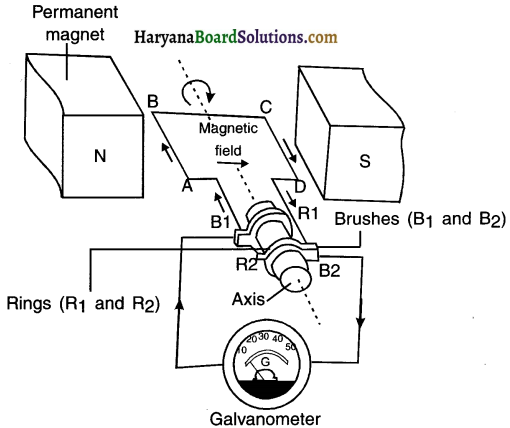
1. An AC electric generator, as shown in the figure consists of a rotating rectangular coil ABCD placed between the two poles of a permanent magnet.
2. The two ends of this coil are connected to the two rings R1 and R2. The inner side of these rings are insulated.
3. The two conducting stationary brushes B1 and B2 are kept pressed separately on the rings R1 and R2 respectively.
4. The two rings R1 and R1 are internally attached to an axle. The axle may be mechanically rotated from outside to rotate the coil inside the magnetic field.
5. Outer ends of the two brushes are connected to the galvanometer to show the flow of current in the given external circuit.
Working:
1. Suppose the axle attached to the two rings is rotated such that the arm AB moves up (and the arm CD moves down) in the magnetic field produced by the permanent magnet. Then the coil ABCD gets rotated clockwise.
2. By applying Fleming’s right-hand rule, we can determine that the induced currents are set up in these arms along the directions AB and CD. Thus an induced current flows in the direction ABCD or say from B2 to B1.
(Note: If there are larger numbers of turns in the coil, the current generated in each turn adds up to give a large current through the coil.)
3. After half a rotation, arm CD starts moving up and AB, down. As a result, the directions of the induced currents in both the arms change. This gives rise to the net induced current In the direction DCBA. The current in the external circuit now flows from B1 to B2.
4. Thus after every half rotation, the polarity of the current in the respective arms changes. Such a current, which changes direction after equal intervals of time, ‘s called an alternating current (abbreviated as AC).
Function of split ring:
The function of split ring is to work as a commutator for reversing the direction of current in the coil after every half rotation.
![]()
Question 12.
Name some devices in which electric motors are used.
Answer:
Electric motors are used in fan, air conditioner, mixer and grinder, washing machine, water-pumps, etc.
Question 13.
A coil of insulated copper wire is connected to a galvanometer. What will happen if a bar magnet is
(i) pushed into the coil,
(ii) withdrawn from inside the coil,
(iii) held stationary inside the coil?
Answer:
(i) Electric current will be induced in the coil and the galvanometer will show a deflection.
(ii) Electric current will be induced in the coil but in opposite direction. The galvanometer will show a deflection in reverse direction.
(iii) No current will be induced in the coil. The galvanometer will not show any deflection.
Question 14.
Two circular coils A and B are placed closed to each other. If the current in the coil A is changed, will some current be induced in the coil B? Give reason.
Answer:
Yes. Current will be induced in coil B.
Reason: When the current in coil A is changed the magnetic field around it changes.
As the two circular coils are placed close to each other, the magnetic field lines linked with coil is also changed. Therefore, sohrie current is induced in coil B.
Question 15.
State the rule to determine the direction of a
(i) magnetic field produced around a straight conductor-carrying current,
(ii) force experienced by a current-carrying straight conductor placed in a magnetic field which is perpendicular to it, and
(iii) current induced in a coil due to its rotation in a magnetic field.
Answer:
(i) Direction of magnetic field:
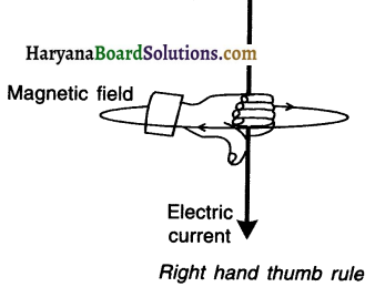
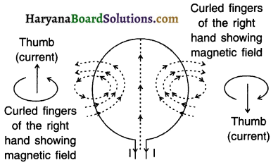
1. The direction of magnetic field associated with the electric current can be found with the help of the ‘Right Hand Thumb Rule’.
2. For knowing the direction of magnetic field, imagine that you are holding the conducting wire in your right hand so that your thumb points in the direction of the current (I), then the direction in which your fingers encircle the wire will give the direction of magnetic field around the wire.
3. The wrapped fingers demonstrate closed loops.
![]()
(ii) Fleming’s left hand rule:
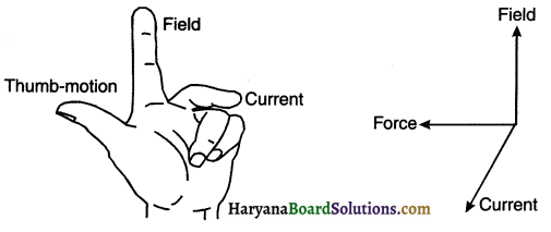
1. Arrange your left hand such that the fore finger, the center finger and thumb remain at right angle to each other.
2. Adjust your hand in such a way that the forefinger points in the direction of magnetic field and the centre finger points in the direction of current, then the direction in which the thumb points will be the direction of magnetic force.
(iii) Fleming’s right hand rule:
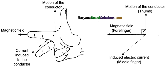
1. The direction of electric current can be found out with the help of Fleming’s right hand rule.
2. Arrange the forefinger, middle finger and thumb of a right hand at right angle to one another.
3. Adjust the forefinger in the direction of magnetic field, and thumb pointing in the direction of motion of conductor.
4. The direction of middle finger will then indicate the direction of induced electric current.
Question 16.
Explain the underlying principle and working of an electric generator by drawing a labeled diagram. What is the function of brushes?
Answer:
Electric generator:
1. An electric generator is a device which converts mechanical energy into electric energy. Principle:
2. The electric generator works on the principle of electromagnetic induction.
Construction:
(Note: The construction and working shown here is of an Alternating Current (AC) generator.)
1. An AC electric generator, as shown in the figure consists of a rotating rectangular coil ABCD placed between the two poles of a permanent magnet.
2. The two ends of this coil are connected to the two rings R1 and R2. The inner side of these rings are insulated.
3. The two conducting stationary brushes B1 and B2 are kept pressed separately on the rings R1 and R2 respectively.
4. The two rings R1 and R1 are internally attached to an axle. The axle may be mechanically rotated from outside to rotate the coil inside the magnetic field.
5. Outer ends of the two brushes are connected to the galvanometer to show the flow of current in the given external circuit.
Working:
1. Suppose the axle attached to the two rings Is rotated such that the arm AB moves up (and the arm CD moves down) in the magnetic field produced by the permanent magnet. Then the coil ABCD gets rotated clockwise.
2. By applying Fleming’s right-hand rule, we can determine that the induced currents are set up in these arms along the directions AB and CD. Thus an induced current flows in the direction ABCD or say from B2 to B1.
(Note: If there are larger numbers of turns in the coil, the current generated in each turn adds up to give a large current through the coil.)
3. After half a rotation, arm CD starts moving up and AB, down. As a result, the directions of the induced currents in both the arms change. This gives rise to the net induced current In the direction DCBA. The current in the external circuit now flows from B1 to B2.
4. Thus after every half rotation, the polarity of the current in the respective arms changes. Such a current, which changes direction after equal intervals of time, ‘s called an alternating current (abbreviated as AC).
![]()
Question 17.
When does an electric short circuit occur?
Answer:
1. An electric short circuit takes place when the live wire and neutral wire of the electric supply line touch each other directly or indirectly via. a conducting wire.
2. This occurs when the plastic insulation of the wires gets torn or there is a fault in the electrical appliance.
Question 18.
What is the function of an earth wire? Why is it necessary to earth metallic appliances?
Answer:
1. The earthing wire is a green colour wire connected to a metal plate. The metal plate is buried deep in the earth near our house.
2. In case, if the live wire touches the metal case of the appliance (i.e. in case of leakage of current), then due to earthing, the current will directly pass into the earth without causing electrical shock to the user.
3. To avoid electrical shocks, metal appliances such as toaster, electric iron, refrigerator, table fan, etc. are connected to the earth wire. Thus, a person is saved from any electrical shocks occurring due to leakage of current.
HBSE 10th Class Science Magnetic Effects of Electric Current InText Activity Questions and Answers
Textbook Page no – 224
Question 1.
Why does a compass needle get deflected when brought near a bar magnet?
Answer:
1. When you bring the magnetic compass near the bar magnet, the magnetic field of bar magnet exerts force on both the poles of the compass needle.
2. The force experienced by two poles is equal and opposite. So, these two forces form a couple and hence deflect the compass needle.
Textbook Page no – 228
Question 1.
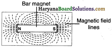
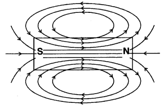
Draw magnetic field lines around a bar magnet.
Answer:
Question 2.
List the properties of magnetic field lines.
Answer:
Characteristics of magnetic field lines:
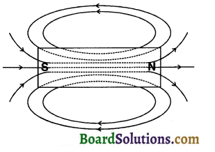
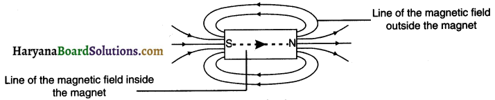
(1) The magnetic field lines outside the magnet starts from the north pole (N) and reach the south pole (S), whereas, inside the magnet, these lines start from south pole (S) and end at north pole (N).
- The inner and outer lines together form closed loops.
(2) The region where the field lines are closer has a stronger magnetic field compared to the region where the field lines are farther.
- Thus the magnetic field is strong near the poles where the lines are quite close to each other.
(3) Magnetic field is a vector quantity. This means it has magnitude as well as direction.
- The tangent drawn at any point of a magnetic field line (the direction of magnetic needle at that point) shows the direction of magnetic field at that point.
(4) Magnetic field lines do not intersect each other.
![]()
Question 3.
Why don’t two magnetic field lines Intersect each other?
Answer:
No, the two magnetic lines of force cannot intersect.
Reason:
If the two magnetic field-lines intersect then it would mean that at the point of intersection, the compass needle would point towards two directions which is not possible.
Textbook Page no – 229
Question 1.
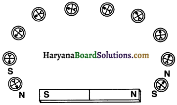
Consider a circular loop of wire lying In the plane of the table. Let the current pass through the loop clockwise. Apply the right-hand rule to find out the direction of the magnetic field inside and outside the loop.
Answer:
1. By applying right hand thumb rule, we can find the direction of the magnetic field inside and outside the circular loop of wire carrying electric current.
2. The magnetic field lines (dotted) are found to be perpendicular to the plane of the paper.
3. The front side of the loop behaves as the south pole where as the back side i.e. the face touching the plane of the table behaves as the north pole.
Question 2.
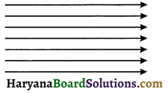
The magnetic field in a given region is uniform. Draw a diagram to represent it.
Answer:
A uniform magnetic field in a given region can be represented by straight, parallel equally spaced field lines.
3. Choose the correct option:
The magnetic field inside a long straight solenoid-carrying current
(a) Is zero
(b) decreases as we move towards its end
(c) increases as we move towards its end
(d) Is the same at all points
Answer:
(d) Is same at all points
Reason: Since the magnetic field line is uniform, represented by parallel equally spaced lines, the current is same at all points.
Textbook Page no – 231.
Question 1.
Which of the following properties of a proton can change while It moves freely in a magnetic field? (There may be more than one correct answer.)
(a) mass
(b) speed
(c) velocity
(d) momentum
Answer:
The correct options are (c) and (d).
Reason: The magnetic force acts perpendicular to the direction of motion of the proton. It does not change its mass and speed but changes its direction of motion. So, both velocity and momentum get changed.
Question 2.
In Activity 13.7, how do we think the displacement of rod AB will be affected if ……………
(i) current in rod AB is increased;
(ii) a stronger horse-shoe magnet is used; and
(iii) length of the rod AB is Increased?
Answer:
(i) When the current in the rod AB is increased, force exerted on the conductor increases.
∴ The displacement of the rod increases.
(ii) When a stronger horse shoe magnet is used, the magnitude of the magnetic field increases. This increases the force exerted on the rod and the displacement of the rod.
(iv) The displacement of the rod will increase, because F α L.
Question 3.
A positively-charged particle (alpha-particle) projected towards west is deflected towards north by a magnetic field. The direction of magnetic field is ……………
(a) towards south
(b) towards east
(c) downward
(d) upward
Answer:
(d) Upward
Reason: As per Fleming’s left hand rule.
Textbook Page no – 233.
Question 1.
State Fleming’s left-hand rule.
Answer:
1. Arrange your left hand such that the fore finger, the center finger and thumb remain at right angle to each other.
2. Adjust your hand in such a way that the forefinger points in the direction of magnetic field and the centre finger points in the direction of current, then the direction in which the thumb points will be the direction of magnetic force.
![]()
Question 2.
What is the principle of an electric motor?
Answer:
Electric motor: An electric motor is a device which converts electric energy into mechanical energy.
Principle :
1. When a current carrying conductor (or a coil) is placed in a magnetic field, the conductor experiences force and it rotates,
2. Electric motor works on the same principle.
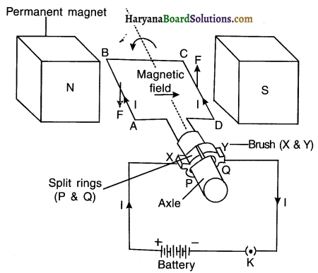
Construction :
1. An electric motor, as shown in figure, consists of a rectangular coil ABCD made from insulated copper wire.
2. The coil is placed between the two poles of a magnetic field such that the arm AB and CD are perpendicular to the direction of the magnetic field.
3. The ends of the coil are connected to the two halves P and Q of a split ring.
4. The inner sides of these halves are insulated and attached to an axle such that they can rotate easily.
5. The external conducting edges of P and Q touch two conducting stationary brushes (i.e.carbon strips) X and Y respectively.
6. Finally, the terminals of the battery are connected with brushes ‘X’ and ‘Y’.
Working : Current in the coil ABCD enters from the source battery through conducting brush X and flows back to the battery through brush Y.
1. The current in arm AB of the coil flows from A to B, whereas in arm CD it flows from C to D, i.e. opposite to the direction of current through arm AB.
2. On applying Fleming’s left hand rule, we find that the force acting on arm AB pushes it downwards while the force acting on arm CD pushes it upwards. As a result, the coil and the axle O, mounted free to turn about an axis, rotate anti-clockwise. At half rotation, Q makes contact with the brush X and P with brush Y. So the current in the coil gets reversed and flows along the path DCBA.
3. The reversal of current also reverses the direction of force acting on the two arms AB and CD. Thus the arm AB of the coil that was earlier pushed down is now pushed up and the arm CD previously pushed up is now pushed down.
![]()
4. Hence, the coil and the axle rotate half a turn more in the same direction. The reversing of the current is repeated at each half rotation, giving rise to a continuous rotation of the coil and to the axle.
Uses: The electric motor is used in appliances such as electric fan, mixer, washing machine, CD player, etc.
Question 3.
What is the role of the split ring in an electric motor?
Answer:
The split ring acts as a commutator. Its function is to reverse the direction of the current flowing through the coil after every half rotation of the coil.
Textbook Page no – 236.
Question 1.
Explain different ways to induce current in a coil.
Answer:
(1) Current can be induced in a coil by moving a magnet towards or away from the coil or vice-versa.
(2) Changing the current in the coil placed near it.
(3) Moving a coil in a non-uniform magnetic field or by changing a magnetic field around steady coil.
(4) Rotating it in a magnetic field or by rotating a magnet placed near the coil.
Textbook Page no – 237.
Question 1.
State the principle of an electric generator.
Answer:
1. A device that converts mechanical energy into electrical energy is called an electric generator.
2. The electric generator works on the principle of electromagnetic induction.
Question 2.
Name some sources of direct current.
Answer:
Electrochemical dry cells, batteries, DC generators, solar cells, etc. are the sources of direct current (DC).
Question 3.
Which sources produce alternating current?
Answer:
Alternating current is produced at AC generators (thermal power plants), car alternators, hydroelectric power plant, etc.
Question 4.
Choose the correct option.
A rectangular coil of copper wires is rotated in a magnetic field. The direction of the induced current changes once In each
(a) two revolutions
(b) one revolution
(c) half rotation
(d) one-fourth revolution
Answer:
(c) half rotation
Textbook Page no – 238.
Question 1.
Name two safety measures commonly used In electric circuits and appliances.
Answer:
1. Installing safety fuse of proper rating
2. Connecting earth wire to all devices that have a heavy power rating.
![]()
Question 2.
An electric oven of 2 kW power rating is operated in a domestic electric circuit (220 V) that has a current rating of 5A. What result do you expect? Explain.
Answer:
1. The current drawn by the oven
\(I=\frac{P}{V}=\frac{2 K W}{220 \mathrm{~V}}=\frac{2000 \mathrm{~W}}{220 \mathrm{~V}}=9.09 \mathrm{~A}\)
2. The current of 9.09 A that the oven draws is much more than the current rating of 5A. As a result, the circuit will get overloaded, heat a lot and eventually trip the fuse.
Question 3.
What precaution should be taken to avoid the overloading (domestic electric circuits?
Answer:
Following precautions should be taken to avoid overloading of domestic circuits:
- Wires and fuse used should be of proper rating.
- Smaller appliances such as TV, fan, bulb, etc. should run on a 5A circuit whereas big appliances like AC, water motor, oven, etc. should run on 15A circuit.
- Too many appliances that have high power rating should not be run simultaneously.
- One should not operate too many electrical appliances on a single socket simultaneously.
Activities
Activity 1.
Aim: To demonstrate that a magnetic field is produced around a current carrying wire.
Material required: A thick copper wire, a compass needle, a plug-key, a resistance wire (Resistor R) and a battery of 6 V.
Procedure:
1. Take a straight thick copper wire and place it between the points X and Y in an electric circuit, as shown in figure.
2. Horizontally place a small compass near to this copper wire. See the position of its needle.
3. Pass the current through the circuit by inserting the key into the plug.
4. Observe the change in the position of the compass needle.
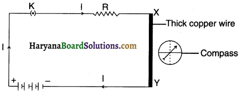
Observation and conclusion:
On passing current through the copper wire XY, the compass needle gets deflected from its position of rest. Since a magnetic needle can be deflected only by a magnetic field, we conclude that the current carrying wire produces a magnetic field around it or it behaves like a magnet.
Activity 2.
Aim : To obtain magnetic field lines around a bar magnet.
Procedure:
1. Fix a sheet of white paper on a drawing board using some adhesive material.
2. Place a bar magnet in the centre of it
3. Sprinkle some iron filings uniformly around the bar magnet Figure. A salt-sprinkler may be used for this purpose.
4. Now tap the board gently.
5. What do you observe?
Observation and conclusion
1. The iron fillings arrange themselves in a pattern as can be seen in the figure.
2. The magnet exerts a force on the iron-fillings scattered around it. This force arranges the filling along definite lines extending from one end to another. The region upto which the fillings got arranged is the region upto where the magnet exerted its force. This region is called magnetic field and the lines are called magnetic field lines.
![]()
Activity 3.
Aim: To draw magnetic field lines of a bar magnet using a compass.
Material: A sheet of white paper, a drawing board, adhesive tape, a bar magnet, a compass and a pen/pencile.
Procedure:
1. Take a small compass and a bar magnet.
2. Place the magnet on a sheet of white paper fixed on a drawing board, using some adhesive material.
3. Mark the boundary of the magnet.
4. Place the compass near the north pole of the magnet. How does it behave? The south pole of the needle points towards the north pole of the magnet. The north pole of the compass is directed away from the north pole of the magnet.
5. Mark the position of two ends of the needle.
6. Now move the needle to a new position such that its south pole occupies the position previously occupied by Its north pole.
7. In this way, proceed step by step till you reach the south pole of the magnet as shown in Figure 9.
8. Join the points marked on the paper by a smooth curve. This curve represents a field line.
9. Repeat the above procedure and draw as many lines as you can. You will get a pattern shown in Figure10. These lines represent the magnetic field around the magnet. These are known as magnetic field lines.
Observation and conclusion:
1. As we move the compass needle towards the poles of bar magnet, the deflection increases. Reason for this is that the magnetic field is stronger near the two poles and so the field exerts large force on the compass needle.
![]()
2. Now, magnetic field is a vector quantity and it has both direction and magnitude. So, the direction of the magnetic field will be the direction in which the north pole of the compass needle moves. Thus, we consider that the field lines emerge from the north poles and merge at the south poles. On the other hand the direction of field line is from its south pole to its north pole inside the magnet. The magnetic field lines form closed curves.
Activity 4.
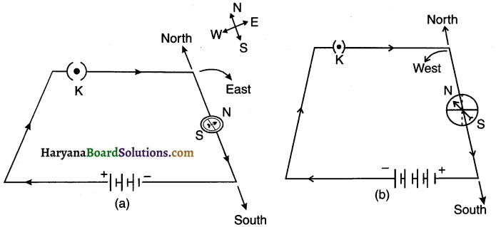
Aim: To show that the direction of magnetic field due to current depends on the direction of the current.
Procedure:
1. Take a long straight copper wire, two or three cells of 1.5V each, and a plug key. Connect all of them in series as shown in Figure (a).
2. Place the straight wire parallel to and over a compass needle.
3. Plug the key in the circuit.
4. Observe the direction of deflection of the north pole of the needle. If the current flows from north to south, as shown in Figure (a), the north pole of the compass needle would move towards the east.
5. Replace the cell connections in the circuit as shown in Figure (b). This would result in the change of the direction of current through the copper wire, that is, from south to north.
6. Observe the change in the direction of deflection of the needle. You will see that now the needle moves in opposite direction, that is, towards the west [Figure (b)]. It means that the direction of magnetic field produced by the electric current is also reversed.
Observation and conclusion:
1. When the current flows from north to south (as shown in figure(a)), the north pole of the compass deflects towards east. On reversing the current the compass needle also deflects in opposite side i.e. towards west.
![]()
2. We conclude that the direction of magnetic field due to the current depends on the direction of the current. So, the direction of magnetic field due to the current gets reversed when the direction of current is reversed.
Activity 5.
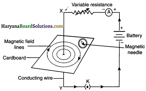
Aim: To study the pattern of magnetic field formed when current passes through a straight conductor.
Procedure:
1. Take a battery (12 V), a variable resistance (or a rheostat), an ammeter (0-5A), a plug key, connecting wires and a long straight thick copper wire.
2. Insert the thick wire through the centre, normal to the plane of a rectangular cardboard. Take care that the cardboard is fixed and does not slide up or down.
3. Connect the copper wire vertically between the points X and Y, as shown in Figure (a), in series with battery, a plug and key.
4. Sprinkle some iron filings uniformly on the cardboard. (You may use a salt sprinkler for this purpose.)
5. Keep the variable of the rheostat at a fixed position and note the current through the ammeter.
6. Close the key so that a current flows through the wire. Ensure that the copper wire placed between the points X and Y remains vertically straight.
7. Gently tap the cardboard a few times. Observe the pattern of the iron filings. You would find that the iron filings align themselves showing a pattern of concentric circles around the copper wire.
8. What do these concentric circles represent? They represent the magnetic field lines.
9. How can the direction of the magnetic field be found? Place a compass at a point (say P) over a circle. Observe the direction of the needle. The direction of the north pole of the compass needle would give the direction of the field lines produced by the electric current through the straight wire at point P. Show the direction by an arrow.
10. Does the direction of magnetic field lines get reversed if the direction of current through the straight copper wire is reversed? Check it.
Observation and conclusion:
(1) It can be observed that the iron fillings align themselves forming a pattern of concentric circles around the copper wire. These circles represent the magnetic field lines.
(i) When we reverse the direction of current through the straight wire, the direction of magnetic field also gets reversed. This can be seen by the deflection of the needle.
![]()
(2) Also note that if we increase the current, the deflection increases and if we decrease it, the deflection decrease. This means the deflection of the needle changes when the intensity of current is charged.
(3) When we move the compass away from the wire, the concentric circles around the current carrying conductor becomes large. i.e. the radius of the circle increases.
Activity 6.
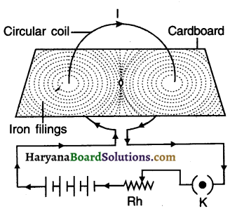
Aim: To study the pattern of the magnetic field lines produced by a current carrying circular coil.
Procedure:
1. Take a rectangular cardboard having two holes. Insert a circular coil having large number of turns through them, normal to the plane of the cardboard.
2. Connect the ends of the coil in series with a battery, a key and a rheostat, as shown in Fig 9.
3. Sprinkle iron filings uniformly on the cardboard.
4. Plug the key.
5. Tap the cardboard gently a few times. Note the pattern of the iron filings that emerges on the cardboard.
Observation and conclusion:
1. As can be seen in the figure, the iron fillings get arranged in a circular pattern.
2. The lines of force around the wire are in the form of concentric circles.
3. At the centre of the loop, the lines of force are almost in the form of parallel straight lines. At the centre the magnetic field is nearly uniform.
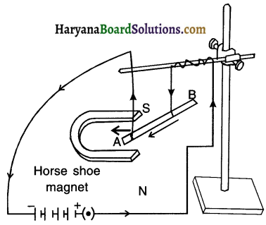
Activity 7.
Aim: To demonstrate the existence of force on current carrying conductor in a magnetic field.
Procedure:
1. Take a small aluminium rod AB (of about 5 cm). Using two connecting wires suspend it horizontally from a stand, as shown in Fig. 12.
2. Place a strong horse-shoe magnet in such a way that the rod lies between the two poles with the magnetic field directed upwards. For this put the north pole of the magnet vertically below and south pole vertically above the aluminium rod (Fig.12).
3. Connect the aluminium rod in series with a battery, a key and a rheostat.
4. Now pass a current through the aluminium rod from end B to end A.
5. What do you observe? It is observed that the rod is displaced towards the left. You will notice that the rod gets displaced.
6. Reverse the direction of current flowing through the rod and observe the direction of its displacement. It is now towards the right. Why does the rod get displaced?
Observation and conclusion:
1. The aluminium rod gets displaced because a force is exerted on the current-carrying rod when it is placed in the magnetic field.
2. When we reverse the direction of current, the direction of displacement of rod i.e. the direction of force on the rod also gets reversed.
3. Suppose we reverse the direction of magnetic field by interchanging the poles of the magnet. Then we observe that the direction of the force on the rod also gets reversed. This means that the direction of force on the conductor depends upon the direction of current and the direction of magnetic field.
![]()
4. The rod gets displaced maximum i.e. the magnitude of the force is maximum when the direction of current is perpendicular to the direction of magnetic field.
We conclude the following:
- A current-carrying conductor experiences a force when placed in a magnetic field.
- The direction of the force and that of the displacement of the conductor depends upon the direction of the current and the direction of the magnetic field.
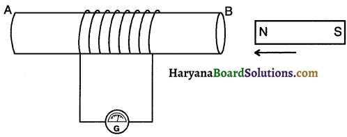
Activity 8.
Aim: To study the phenomenon of electromagnetic induction.
Procedure:
1. Take a coil of wire AB having a large number of turns.
2. Connect the ends of the coil to a galvanometer as shown in Figure.
3. Take a strong bar magnet and move its north pole towards the end B of the coil. Do you find any change in the galvanometer needle?
4. There is a momentary deflection in the needle of the galvanometer, say to the right. This indicates the presence of a current in the coil AB. The deflection becomes zero the moment the motion of the magnet stops.
5. Now withdraw the north pole of the magnet away from the coil. Now the galvanometer is deflected toward the left, showing that the current is now set up in the direction opposite to the first.
![]()
6. Place the magnet stationary at a point near to the coil, keeping its north pole towards the end B of the coil. We see that the galvanometer needle deflects toward the right when the coil is moved towards the north pole of the magnet. Similarly the needle moves toward left when the coil is moved away.
7. When the coil is kept stationary with respect to the magnet, the deflection of the galvanometer drops to zero. What do you conclude from this activity?
Observation and conclusion:
1. When we move the magnet towards away from the coil or when we move the coil towards/away from the magnet, the magnetic lines of force passing through the closed coil gets charged.
2. This induces potential difference in the coil which in turn induces current in the circuit.
3. We can observe the presence of current in the galvanometer needle.
4. The needle shows no movement when both, the coil and the magnet remain stationary.
5. We conclude that when there is no change in the magnetic lines of force passing through the coil, no potential difference is induced and hence no current is induced.
Activity 9.
Aim: To study the phenomenon of electromagnetic induction.
Procedure:
1. Take two different coils of copper wire having large number of turns (say 50 and loo turns respectively). Insert them over a non-conducting cylindrical roll, as shown in Figure. (You may use a thick paper roll for this purpose.)
2. Connect the coil-i, having larger number of turns, in Figure. Current is induced in cou-2 when current in coil-i is changed series with a battery and a plug key. Also connect the other coil-2 with a galvanometer as shown.
3. Plug in the key. Observe the galvanometer. Is there a deflection in its needle? You will observe that the needle of the galvanometer instantly jumps to one side and just as quickly returns to zero, indicating a momentary current in cou-2.
4. Disconnect coil-i from the battery. You will observe that the needle momentarily moves, but to the opposite side. It means that now the current flows in the opposite direction in coil-2.
Observation and conclusion:
1. Coil 1 is called primary coil whereas coil 2 is called secondary coil.
2. When the key is plugged, the needle of the gets galvanometer deflected to one side and then quickly returns of zero. This indicates a momentary current in coil 2.
3. When coil 1 is disconnected from the battery, the needle of the galvanometer moves to the opposite side. This means, now the current flows in the opposite direction i.e. in coil 2.
![]()
4. In short in this activity, we observe that as soon as the current in coil 1 reaches either a steady value or becomes zero, the galvanometer connected to coil 2 shows no deflection.
Conclusion:
(a) A potential difference is induced in coil 2 whenever the electric current through the coil 1 changes.
(b) As the current in coil 1 changes, the magnetic field associated with it also changes. At that time, magnetic field lines around coil 2 also change. Thus, the change in magnetic field lines associated with the secondary coil is the cause of induced electric current in it.